Rants and Raves regarding carbide inserts, cbn inserts, ceramic inserts, cermet inserts, and inserts in general. Occassionaly will take about nothing, and sometimes other cutting tools. Most of all a resource for information on cutting tools.
Titanium and titanium alloys are most often found in aerospace applications due to its lightweight and high strength.
However, other industries are discovering the benefits of titanium as well. One of the more common alloys is Ti 6AL-4V. It is generally machined at a hardness ranging from approx. 28 to 37 Rc.
One the characteristics that makes titanium difficult to tap is its tremendous elastic memory. When tapping, the material closes tightly around the cutting tool, generating friction and heat, resulting in increased wear of the cutting edges. This material also easily work hardens.
To successfully tap titanium, a tap specifically designed with additional clearance to overcome the extreme elastic memory of the material is recommended.
Tap clearances would include extra back taper of the threads from the front to the back of the thread section, full radial clearance in the threads across the tap lands, and additional relief in the tap chamfer area.
All of these features are used to reduce friction and heat. In some cases, larger H limits might be required to overcome the shrinkage.
Premium grade materials are also used for heat and wear resistance. Obviously we offer these in our standard product lines.
Lubrication and proper pre-tapped hole size are vital to success. A compatible tapping fluid should be used that provides plenty of lubrication to reduce friction.
The drill should be selected to produce the largest hole size that is allowed by the thread class callout (2B or 3B).
Due to the additional clearances required on these tools, positive feeding of the tap is highly recommended.
Aluminum is Inexpensive, Lightweight and is Formable at Cold Temperatures
Aluminum is one of the most common materials used in manufacturing strong, lightweight parts. PMF manufactures parts made purely of Aluminum alloys as well as parts made from two or more materials such as Stainless Steel and Aluminum.
Common Forms of Aluminum (in various tempers) 6000's, 5000's, 1000's, 2000's, 3000's, 7000's
Benefits of Aluminum
Inexpensive
Lightweight
Formable at cold temperatures
Considerations of Aluminum
Softness can lead to tearing
Low tensile strength (approx. 1/3 that of steel)
Applications of Aluminum
Military munitions
Aerospace
Microelectronics
Automobile parts
Many others
Looking for inserts for machining aluminum? Find them at pgsTools.com. Your choice
Definition: A widely used process for the surface hardening of steel. The components are heated by means of an alternating magnetic field to a temperature within or above the transformation range followed by immediate quenching. The core of the component remains unaffected by the treatment and its physical properties are those of the bar from which it was machined, whilst the hardness of the case can be within the range 37/58 Rc. Carbon and alloy steels with a carbon content in the range 0.40/0.45% are most suitable for this process.
Often taps get the blame for poor thread quality or rejected threads and it is natural to look to the tap itself as the culprit. Actually, the tap is often the victim of a badly drilled hole. You can't produce a great thread out of a bad hole! Following are some issues and possible resolutions.
1. A dull drill will create a very rough torn hole. Expect poor or incomplete threads.
2. A reground drill must be perfectly concentric. The cutting lips must be of equal length and be ground to the same angles. Failure to create a concentric point will cause the drill to cut on one side more than the other and a crooked, bent hole will result making an attempt to tap that hole very difficult. This can also produce an oval egg shaped hole.
3. Castings sometimes have a tapered hole so the part will release easily. Threading requires straight walls and tapered walls are impossible to thread correctly.
4. Undersized holes are difficult or impossible to thread.
5. Holes that have had the surface work hardened by too high a temperature in the drilling process can become too hard to thread effectively.
6. Materials that shrink or close-in after drilling are undersized for tapping.
7. Holes too near welding or flame cut areas can become hardened and difficult to thread. Bottom line, consider good hole quality as essential in producing quality holes and if you are having difficulty, dont forget to investigate the drilling process in addition to the tap.
When producing internal threads, selecting the right thread mill diameter insures it will operate efficiently.
Thread mills are usually offered in several cutting diameters for a given threads per inch. Smaller diameters are used for small thread sizes, such as 3/8-16 NC.
A larger tool diameter could be used for producing a 3/4-16 NF. However, the smaller thread mill could be used to produce the larger 3/4-16 as well.
Generally, for coarser pitches (coarser than 14 TPI), selecting a cutting diameter no larger than 70% of the nominal thread size to be produced is recommended.
For finer pitches, the thread mill can be as large as 75% of the nominal diameter. Although the tool has radial clearances similar to end mills, if the tool diameter is too close to the thread diameter, the tool may rub, producing more heat that could result in excessive wear.
This rubbing may also distort the thread form affecting the thread angle.
The question is, should the largest thread mill that will fit the hole be used? The answer is, not necessarily!
For the greatest efficiency, smaller mills will remove more cubic inch of metal than a larger one, resulting in greater productivity.
There will be more clearance for the tool and more space for coolant and chips.
However, to optimize the tool, it will be rotating much faster, which may exceed the capability of the machine.
Also, the thread length on the tool may be too short for the thread depth required.
On the other hand, the larger diameter thread mill will minimize deflection, particularly on coarse thread series, but is more prone to rubbing and chip congestion.
1. Use a tool that has higher thermal-conductivity Low thermal-conductivity of stainless steels accelerates tool wear resulting from a decline in hardness of the cutting edge of an insert, this is due to heat piling up. It is better to use a tool that has higher thermal conductivity and with enough coolant.
2. Sharper cutting edge-line It is necessary to utilize larger rake-angles and wider chip-breaker lands to reduce cutting-load pressue and prevent build-up on the edge. This will help provide better chip control to an operator.
3. Optimal cutting condition Inappropriate machining conditions like extremely low or high speeds or low feeds can cause poor tool life due to work hardening of work pieces.
4. Choose an appropriate tools Tools for stainless steel should have good toughness attributes, enough strength on their edge line (cutting edge) & a higher film adhesion.
Korloy offers three grades turning stainless steel:
Lose a screw, lock pin, or clamp for your boring bar or toolholder? Wondering what the heck a lock pin or clamp is? Use the following guide to help you sort out what you may need in replacement parts for boring bar or tool holders. Find a definition of each component below the picture.
Here is a diagram (click on image to enlarge) of a Multi-Lock Tool Holder courtesy of Dorian Tool:
INSERT Either conventional type or chipbreaker type may be used.
LOCK PIN A solid locking pin for permanent locating of the insert.
SHIM SCREW Reusable shim screw locks carbide shim into toolholder.
CARBIDE SHIM Forms a firm seat for insert. Fastened to the shank, but easily replaceable. Protects against damage to toolholder.
CLAMP Maximum retention clamp is made of high alloy steel, heat treated. Broad clamp nose provides positive clamping action. Clamp is positioned to allow for maximum insert retention, with or without chipbreaker.
CLAMP SCREW Rugged Clamp Screw provides maximum clamping strength.
CHIPBREAKER Solid carbide, for use when chip control is needed. Available in a range of standard chipbreaker widths.
Most toolholders and boring bars accept generic shim seats, screws, clamps, and pins. This includes tools from Valenite, Sandvik, Kennametal, and Iscar. Check your manufacturers catalog to be sure of the replacement items part number.
VALENITE INTRODUCES NEW TURNING GRADES FOR FINISHING, SEMI-ROUGHING STAINLESS STEELS
Valenite LLC has introduced two new tooling grades—expanding its targeted and application-specific lineup that allows users to better match machining operations and workpiece materials with tooling inserts for optimum production efficiencies, quality and economies. The new cutting technologies are the ValProTM VP8515 and VP8525 MT-CVD series of inserts. Both are being developed to augment the existing VP8535 grade and provide a complete range of turning capabilities for 304 and 316 stainless steels, Inconel and heat resistant alloys. The VP8515 is for finishing operations and the VP8525 is used for general duty semi-roughing/finishing. The existing VP8535 is for heavy metal removal tasks and roughing operations.
The VP8515 grade is set for high cutting speed (>200 m/min) at typical finishing
cut depths and has broad applicability with F5, M4, M6, M8, PM2, PM5 geometries. This grade is ideal for continuous turning of austenitic and duplex stainless steels at higher speeds providing reliable and predictable performance, with extended insert service life. Inserts using VP8515 grade have a thin yellow TiN outer coating for easy visual wear identification, an Al2O3 layer for thermal protection, a fine MT-CVD TiCN coating that helps to prevent flaking and reduces flank wear. Also incorporated in the tooling is a gradient area for added surface toughness, and a hard substrate offering greater resistance to wear and plastic deformation.
The TiCN/Al2O3/TiN coating is formulated specifically for turning of stainless steels and to resist sticking, notch wear and edge build-up, for enhanced hardness when hot.
The VP8525’s performance characteristics deliver high cutting speeds (>150 m/min) with mid- to large cutting depths...inserts have M4, M6, M8, R9, PM4, PM5 geometries to cover a myriad of cutting parameters. This grade is a basic choice for general duty M-class turning—continuous or intermittent cutting of austenitic and duplex stainless steels. These tools reduce the risk of plastic deformation and, like the VP8515, provide reliable performance and extended tool life. The VP8525 grade has similar coating technologies, layering and substrate construction as the finishing grade, including the TiCN/Al2O3/TiN coating for the efficient turning of stainless steels.
To produce hubs, rods, bushes, pulleys and shafts, CNC turning is utilized where the lathe generates materials after inserting the single cutter point in to the material turning. The procedure of cutting is executed through a cutting tool which is applied either parallel or at right angle to the axis, of work piece. The tool may also be fitted at an angle relative to the work piece axis for the machining angles and tapers. The work piece may be of any cross section, but the machine surface should be straight and tapered.
There are various shapes available in CNC like pointed, simple, radius with profile added with threaded surface, curve and fillet. CNC machining is more economical than the CNC milling for producing the actual form through CNC turning. The material used for CNC turning possesses various qualities like material of work piece should be firm and can be of solid plastics. For the short running procedure of the mill, arrangements or alternative machine should be kept. CNC turning reduces the cost by minimizing the design elements.
CNC turning procedure is done through applying pressure on the work piece or the weaker material to form the flexible shapes of the material. Sometimes through CNC, the cut surface is formed by applying the helical feed as it results in rotation. The cutting procedure through which the work piece is eliminated from a material block by the help of the rotation of the tool is known as CNC milling. The work piece can rotate in perpendicular or circular way to produce different shapes and sizes. The cutting tool generally rotates in the CNC milling at an axis in a perpendicular form on the podium to generate various structures.
Variety of shapes that can be formed through CNC milling is 3D or 2D and some compound structured material. CNC milling for short procedure is also very economical. It is utilized to make different parts of engine, multifaceted mechanisms, enclosures and mold and custom tooling.
Thus, is a very effective procedure to make various machine parts of various shapes which is very significant for running the machine.
Get carbide inserts or cutting tools for your cnc machines at www.pgstools.com. PGS sells cutting tools and carbide inserts from Korloy, Taegutec, Valenite, Iscar and generic carbide inserts online at discount prices.
Whether you’re making brake discs and flywheels in grey cast iron, or crank shafts and wheel hubs in nodular cast iron, there is always a successful solution.
Over the years there have been a number of CBN grades made available for machining cast iron with CBN. Most notably are DR-80 and DR-85. These grades are made for the following applications:
For rough and semi-finish turning, milling, grooving and boring of hardened ferrous and certain softer ferrous materials:-
Martensitic cast irons - Ni-hard - High chrome Chilled and heat treated cast irons
Fully hardened cold-work tool steels
Bearing steels
High speed steels (continuous cutting only)
Martensitic stainless steels
Cobalt and nickel based hard facing alloys
Fully pearlitic grey cast iron
DR-80 & DR-85 are high CBN content materials, diffusion bonded at the manufacturing stage to a tungsten carbide substrate. DR-80 is (80% CBN) has a greater particle size than DR-85, (85% CBN). DR-80 is better for hardened steel, but DR-85 has better wear characteristics when machining cast iron with CBN, particularly when the stucture contains Ferrite. For more information on machining with CBN Inserts please visit David Richards Engineering UK or David Richards Engineering US
Boring out cylinders to accept oversized pistons or sleeves has long been a common practice in the engine rebuilding business. Boring allows worn blocks to be salvaged, and stock cylinder bores to be enlarged for more displacement. More recently, boring is also being used to install special cylinder liners with hard surface treatments in high performance racing engines. The hard liners almost eliminate ring and bore wear so the engine can run race after race with no increase in bore clearances blowby.
Like most other machine tools in today's shops, the equipment used to bore engines is also evolving to keep pace with changes in engine technology and the aftermarket. Small shops want equipment that is versatile and can do more than just bore holes. For this end of the market, combination boring/milling machines have become popular. At the other end of the spectrum, production engine remanufacturers (PERs) want equipment that works harder, works faster and requires less operator input. For this type of user, automated high speed boring equipment provides the needed boost in productivity and quality.
Tooling has also been improving. The latest generation of coated carbide inserts provides longer life and better cutting action. For high speed boring, polycrystaline diamond (PCD inserts) provides the longevity needed for this type of operation. The speed at which the boring bar turns has a significant impact on tooling life. High speeds just kill the bits unless you use a PCD or cubic boron nitride (CBN inserts) type of insert. The high speed boring machines that go up to 1,500 rpm need these type of inserts.
Sumicrystal UP Cutting Tool Blanks 2 pictures above
What is this stuff? Synthetic Monocrystalline Diamonds: Perfectly flat, defect free synthetic diamonds- Monodie-100 and Monodie-111 from DeBeers, U.K. and Sumicrystals from Sumitomo Electric Industries, Limited., Japan-are used for specific customer requirements.
What is a PD Dresser Blank? The Sumicrystal PD dresser blanks are single crystal diamonds processed into the shape of a long, thin prism. They provide automated and high precision dressing through reliable performance and long tool life.
Ok, now what about the UP Cutting Tool Blanks? The Sumicrystal UP cutting tool blanks are just that...cutting tool blanks. They were developed by Sumitomo Electric to provide high performance and reliability for high precision cutting tools. They work well in ultra-precision machining processes, for machining products such as memory discs and polygon mirrors.
Now that I know, where can I get it? Interesting that you should ask. The pictures above are tools that are available. If you are s, interested in purchasing these tools, please contact us a sales@pgstools.com.
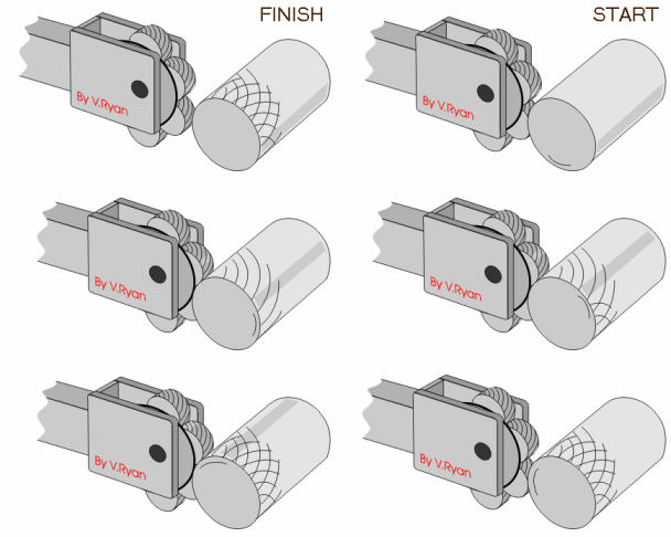
A knurling device is used in combination with a lathe to stamp the ends of metal tubes and other shafts. The stamped ruts might also act as hand grips for the user or superior grip for rubber and the plastic covers. The knurling tool itself comprises of various rotary cutters that are held against the metal shaft as it turns on the metal lathe at a moderately slow speed (500 rpm on average). Turning is a technique by which cylindrical pieces of metal lathe or wood are spun in place by a variable-speed electric motor. As the piece spins, a variety of cutting tools could be placed against it to take away fabric or cut shapes. A knurling tool falls among an engraver and an embosser.
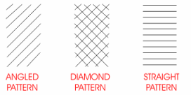
There are usually three shapes created by most knurling tools - straight lines, slanting lines and a diamond pattern. Knurling tools do come in different range of sizes and amazing designs, depending on the basis of the piece. The diamond pattern is mainly familiar with hand grips as it generates the most grips among a user's hand and the shaft. Diagonal and straight knurls are usually used to give additional traction to an outside handle or other connective piece. In order to generate a knurl pattern, the metal lathe should hold the metal piece entirely straight - a condition machinist call 'true'. As the lathe begins to roll, a particular holder for the knurling tool is attached to the perform table.
The knurling tool itself is fixed into the lathe and cautiously directed to the turning piece with a tiny crank. Since knurling is extremely a rough process, the machinist must use a liberal supply of machine oil on the rotating shaft. A knurling tool hardly ever makes a complete imprint the first time it is pressed against the shaft. Machinists usually make several passes with the knurling tool, allowing the individual cutters to make small bites into the metal. A knurling tool is best compatible for softer metals such as aluminum or normal grade steel. Hard metals such as titanium would most probable ruin the tool before any embossing could take place.
About the Author: John Russel is a Copywriter of Lathe chucks. He written many articles in various topics. For more information visit: Chuck manual contact him at aworkholding@gmail.com
In every machining system, one simply can't ignore the important role that cutting tools play. Oftentimes, the quality of a finished product would rely on the quality of the cutting tools. The quality and the performance of cutting tools would also directly affect a machining system's overall productivity. It is because of their importance that manufacturers would take into consideration several criteria before eventually buying a piece of cutting tool for their machining system. Included in these criteria are the tools ability to last long under rigorous operating conditions and their capability to perform at very high speeds. Also important is the tool's resistance to wear and tear, including resistance to breakage, edge and flank wear, cratering or top wear, chipping, built-up edge (BUE), deformation, and thermal cracking.
1. Kinds Of Tools
As the demand for better cutting tools increase, cutting tool suppliers also continuously develop products that can pass manufacturers' demands. Through the years, a lot of materials for the manufacture of cutting tools have been experimented upon; some have passed the standards while others were simply dropped. Today, there are only two types of cutting tools heavily favored in the machining industry: high speed steel (HSS) cutting tools and carbide cutting tools; and it seems that carbide cutting tools have slightly overtaken the other in popularity. So, what advantages do carbide cutting tools have over their HSS counterparts? Considering their lead in popularity, it is clear that the benefits of carbide cutting tools outnumber that of HSS cutting tools. And we'll understand these benefits better if we know what carbide really is.
In chemistry, carbides refer to any group of compounds made up of carbon and one other element that can be a metal, boron, or silicon. There are actually many compounds belonging to this group, among the more popular of which includes:
In the 20th century, carbides have been used for a lot of industrial applications. Carbides used in industrial applications are often called cemented carbide products and are classified in three major grades:
- Wear grades
Used primarily in dies, machine and tool guides
- Impact grades
Higher shock resistance carbide products used for dies, particularly for stamping and forming
- Cutting tool grades
Carbide tools used for cutting
4. Carbide Cutting Tools
Cutting tool grades of carbides are further subdivided into two groups: cast-iron carbides and steel-grade carbides. As their name implies, cast-iron carbides are specifically made for cutting cast-iron materials. These carbides are more resistant to abrasive wear, protecting the carbide cutting tool from edge wear due to the high abrasiveness of cast-iron. Steel-grade carbides, on the other hand, are specially made to resist cratering and heat deformation that may be caused by the long chips of steel on higher cutting speeds. Whichever grade of carbide is used in a carbide cutting tool, the main carbide material used in its manufacture is tungsten carbide (WC) with a cobalt binder. Tungsten carbide is well known for its hardness and resistance to abrasive wear. Cobalt, on the other hand, is used to further toughen the tool's surface.
5. Other Variants
Aside from tungsten carbide and cobalt, other alloying materials are added in the manufacture of carbide cutting tools. Among them is titanium carbide and tantalum carbide. Titanium carbide helps the carbide cutting tool to resist cratering while tantalum carbide can reduce heat deformations in the tool. Also commonly used in the cutting industry today are coated carbide cutting tools. Aside from the basic carbide materials, titanium carbide, titanium nitride, ceramic coating, diamond coating or titanium carbonitride are used as coating materials. The different coating materials aid the carbide cutting tool differently, although they are generally used to further toughen the cutting tool.
6. Benefits of Carbide Cutting Tools
- Toughness
- Exceptional resistance to abrasion
- Superior wear resistance
- Resistance to cratering
- Resistance to thermal deformations
- High modulus of elasticity
- Chemical inertness
- Torsional strength twice that of HSS
- Compressive strength
Plastics and reinforced plastics can be machined with PCD Inserts and PCD tooling.
The general perception is that plastic materials are easy to machine. However, soft plastics are not always so stable, and the machining process, which always generates heat, can affect dimensional and material properties like surface texture and colour, if the correct cutting tool is not applied.
PCD tools are particulary effective on abrasive plastics where plastics are reinforced with carbon fibres (CF) or glass fibres (GF).
Welcome to a new section of carbideinserts.blogspot.com. Our focus with these blog posts will be to provide application examples with insert type, speeds and feeds, to hopefully give you a baseline and to help you with your own machining applications. We will add these machining tips on a regular basis, so check back often!
This blog entry focus is on machining the following:
Cemented carbide with a Co content of less than 17%:
1. First choice for machining is CBN 2. Should use a round cbn insert 3. The insert should have a chamfered cutting edge 4. Machining with coolant is recommended 5. Chamfer the workpiece at entry and exit point.
Should you require further assistance in choosing an insert or pricing. Please contact the experts at David Richards Engineering.
At first it might seem that machining fiber-filled composites with hard cutting tools would be a recipe for disaster. Developers of cutting methods and tools for composites face all kinds of problems. A composite's fiber layers can delaminate from the machined surface; the fibers or other hard reinforcements are abrasive and reduce tool life considerably; and the combination of hard and soft materials that make up a composite complicates the best choice of tool and machining parameters.
What do I use then?
Diamond will interact with carbon in ferrous materials, so its use is largely restricted to nonferrous workpieces. Today, the automotive industry is the major user of diamond tools in machining components made of aluminum-silicon alloys--in particular the 300 series of aluminum alloys. Major applications for silicon-containing aluminum materials are in pistons, engine heads, blocks and manifolds, wheels, and transmission parts. Other significant applications for diamond tools are in machining graphite, carbon-carbon (C-C) composites, metal-matrix composites (MMC), and fiber reinforced plastics (FRPs).